To paraphrase Helen Keller: the only thing worse than being a blind robot is to be a robot with sight, but no vision.
Machine vision is the combined methods for taking in video or still image data and translating it into some meaningful interpretation of the world that a computer can understand. Some of the most popular applications include face recognition, glyph tracking, 2D barcoding, navigation, and in recent years, using artificial intelligence algorithms to be able to describe the objects in a picture using computers. My thinking is that if I can understand the tools of machine vision, then I can extend those tools to robotics problems I’m working on like object grasping and manipulation and navigation. Machine vision algorithms are built into many sophisticated software packages like MatLab or LabView, but these are typically VERY expensive, making them completely inaccessible to me. Fortunately, the principles of machine vision are well-documented and published outside of these expensive software packages, so at least there’s hope that if I work for it, I can build up my own library of machine vision tools without spending a fortune.
Since I’m building up this library for myself, I want avoid having to rewrite the programs to adapt them to any hardware that I might have connected to a robot including Windows and Linux machines or system-on-a-chip computers like Raspberry Pi, BeagleBone Black, or Intel Edison. My programming experience has been based in Windows computers, so I realize that the languages I’m familiar with won’t be directly useful. I chose Python because it’s open source, free, well-supported, popular, and has versions across all of the hardware platforms I’m concerned with.
I chose finding a color marker as my first venture into the murky waters of machine vision. The problem is pretty simple: use the webcam to find a color, send the coordinates to a robot arm, and move the robot arm. Au contraire, mon frere. That is not all.
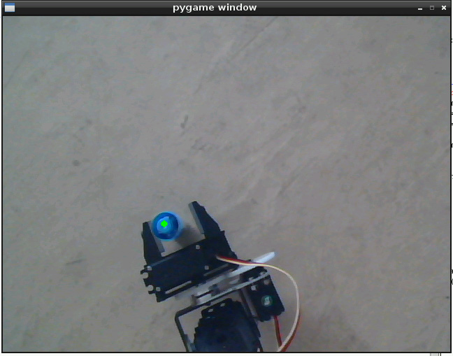
The first hurdle to overcome is capturing the webcam data. Fortunately, the Python module Pygame is incredible for doing just that. It allowed me to capture and display a live feed of images from the webcam and superimpose drawing objects over the images so I could easily understand what I was seeing. Most of the code I used came from the tutorial programs in one form or another. In the picture above, you can see the webcam image shown with the superimposed green dot representing the center of the marker.
The second battle to face is lighting. When we look at an object, we are actually seeing the light it’s reflecting. What that means is that when you change the light level or the color content of your light source (for example: use yellow instead of white), suddenly your robot will get lost because the color it “sees” is different than the color it expects. So, now we have to add a step to calibrate the vision system with it’s marker every time we run the program in case the light levels have changed between runs.
The next challenge comes in the form of coordinate systems. When we look at the image that the webcam captures, we can get the position of the object in what I’ll call webcam coordinates. Webcam coordinates are basically the count of pixels in the x- and y-axis from one of the corners. However, the robot arm doesn’t know webcam coordinates. It knows the space around it in what I’ll call robot coordinates, or the distance around the base measured in inches. In order for the computer to provide the arm with something that makes sense, we’ll have to be able to translate webcam coordinates into robot coordinates. If your webcam and arm have parallel x- and y-axes, then conversion may be just scaling the pixel count linearly. If the axes aren’t parallel, then a rotation will be needed. I kept the axes parallel and simply put a ruler down on the surface and used that to “measure” the distance that the webcam sees, then divided by the number of pixels in that axis.
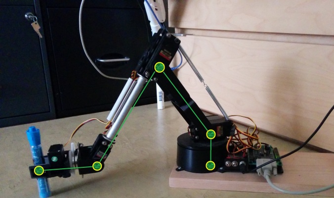
The final roadblock is when you go to make the arm move to the location you’ve given it. The solution to this problem could be as simple as geometric equations or as complicated as inverted kinematic models. Since both methods relate to the movement of the arm, I’ll just call them both kinematics. Even though this will probably be the hardest challenge to overcome, you should probably take it on first since you’ll be able to use the kinematic model of the arm to simplify many other programs you may have for the same arm.
The idea behind kinematic modeling is that you want to write a group or system of equations that tell you what angles to move the arms to so the end of the arm is in a particular position and orientation. In general terms, if you want a robot that can move to any position in a plane (2D), it needs to have at least 2 degrees of freedom (meaning it has 2 moving joints) or if you want to move to any position in a space (3D), it needs to have at least 3 degrees of freedom. In my case, my arm is a 5 degree of freedom arm (meaning it has 5 moving joints) and that makes it particularly complicated to use a purely mathematical inverse kinematic model because I could move to any position in the space around my robot (3D), but I’d have multiple solutions to the equations. I chose to constrain the arm to 3 degrees of freedom by forcing the gripper to have a particular orientation. Then it became easier to model it geometrically.
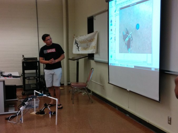
The program I wrote works fairly well. It’s able to find objects of many colors and it’s pretty entertaining to watch it knock over the marker and chase it outside the field of view. I demonstrated it at the August meeting of the Robotics Society of Southern California which meets every month on the second Saturday.
If you have any suggestions on an application for color marker tracking or if you’d like to know more about this project, please leave a comment below.
That was my project day!
If you liked this project, check out some of my others:
The ThrAxis – Our Scratch-Built CNC Mill
Did you like It’s Project Day? You can subscribe to email notifications by clicking ‘Follow’ in the side bar on the right, or leave a comment below.


