The ThrAxis – Our Scratch-Built CNC Mill

As it turns out, you CAN make a CNC machine on a shoestring budget! It just takes a lot of time, reading, effort, and… time.

Working the ThrAxis

Taking the ThrAxis for a Jog

The ThrAxis (Three-Axis) is a vertical milling machine made mostly from materials from hardware stores. The spindle is a Harbor Freight rotary tool and the motors and controllers are surplus and eBay finds. We made it during lots of late evenings using mostly handheld power tools and “garage precision”. It was a fun project for me to work on with my wife and it’s become a handy tool. I’ve found that it has accelerated my ability to realize my project ideas and has made it much easier to make things with the personal touch. We’ve made toys, art, and mechanisms and we have plans for much much more.
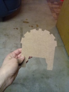
Silhouette Cutout Lion Archway
Cutting out the Silhouette of a Lion Archway Lion Archway Cutout

Why would you make a CNC machine in your shop? It seems like such a daunting job and what the heck would you do with it when you got it? These are the questions I heard when I brought up the ThrAxis to most people. They were right to question because it’s not an easy job. Since working on projects is what I do for fun, the doing and the why were a given for me, but I found it hard to explain. CNC machining allows you to make amazing things; things more precise, rapidly, numerous, and intricate than a person could make by hand. Of course you’re limited by a spinning tool and how far your machine can move, but it’s way more capable than a handsaw and a Dremel tool. My first inspiration was bloodying my fingers forever bending little 1/2″ long wires for RadioShack prototype circuit boards, then chemical etching circuit boards by hand (having only about a 10% success rate), and then spending $100+ on professionally-made circuit boards made me realize that there has to be a better way to get my ideas from breadboard to circuit.

First, there was the ‘buy a CNC machine online’ fiasco. Basically, I saved up a lot and found a few companies online who were selling CNC milling machines. I found one that was in my price range, but the lead time was months. BIG MISTAKE. And I had to pay the full amount up front. RED FLAG. I didn’t hear a peep for a while (eek!) and when I finally reached out, I got no response. I thought my money was safe because I used PayPal to send it. Wrong again! PayPal only guarantees purchases made on eBay. Eventually, I used the refund processes in PayPal to get my money back and got very very lucky, but my experience definitely left a bad taste in my mouth.

Then I started to think seriously about making one on my own. Mostly, though, I blame Make Magazine for my inspiration to do it myself. Since the first issue of my subscription, I’ve seen featured projects for dozens of gantry-style CNC router tables. Throw in the discovery of surplus electronics websites like all electronics and goldmine electronics and I was on a collision course. The final straw was finding the instructable article by Tom McGuire. We liked his design because the boom-style tool holder seemed more stable than the gantry-style CNC router projects we had seen (necessary for making circuit boards). It also has fewer moving parts than the gantry-style CNC routers which means fewer bearings and fewer opportunities for misalignment. The use of the inexpensive rotary tool instead of a router was also a big deal because it meant we could build something that would fit in our tiny workshop.  After a couple of coffeehouse design sessions with my wife, we had some plans and bought the parts to get it done.

I’d been toying with the idea of making a CNC mill for years, but to get this project up and running took about 4 months from drawing up plans to cutting out a part, $250, and a dozen stops at the hardware on the way home from work. Just like the reference instructable, the frame is made from black steel pipe, the stages are made from HDPE, and the screws are 1/4″-20 threaded rods. We added our own features and changed the size of the shapes around to suit our needs, though. We opted for some thinner, leaner materials in the interests of cutting costs. We also took some other liberties with the design, for example the use of 1/4″ fuel line as a motor coupler didn’t seem like a winner, so we used some 1/4″-20 threaded couplers half drilled out with set screws in the shaft section instead. My favorite feature is the bearings: they are actually skateboard wheel bearings. We got a box of 8 of them for $12!

Here’s a brief bill of materials of what we used:

  • 3/8″ HDPE sheet for all of the stages
  • 3/8″ architectural C-channel for the linear guides
  • 1/4″-20 threaded rod for the linear drive screws
  • 3x 1/4″-20 couplers for linear drive nuts
  • 3x 1/4″-20 couplers half-drilled out to 1/4″ with #6-32 set screw hole for motor coupler
  • 8x skateboard wheel bearings
  • lots of washers to level the stages
  • 2′ x 2′ sheet of 1″ MDF for a foundation
  • 3x 3.5A stepper drivers from AutomationDirect
  • Power supply for stepper drivers also from AutomationDirect
  • circuit breaker
  • logic level converter built around a 74LV125AN buffer
  • E-stop button
  • 6 limit switches
  • Shielded cable for stepper motors
  • 6′ of T-slotted track

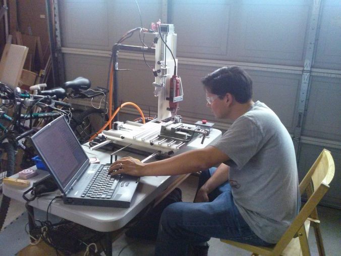
Fortunately, there is so much material online regarding CNC milling and making CNC machines that we were able to get over almost all of the little roadblocks. We were able to assemble it using hand tools, a cordless drill, drill press, a level, and a roofer’s speed square. We had a few occasions to use some taps, too. We are using the TurboCNC software graciously provided to the community for free by DAK Engineering to interpret the g-code on a Windows 95 laptop (a dinosaur, to be sure) which sends the commands through the parallel port to a scratch-built voltage logic level converter to step it up from 3V output to 5V, then into the stepper driver cards. The reason we are using the Windows 95 computer is because we have it and the free TurboCNC software runs in DOS mode, which isn’t available on modern computers.

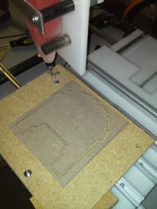
After we got it running, the first part I made was a raised ‘E’ logo that I use to mark my prototypes. That was my wife’s idea. It was a good test of the ThrAxis’s capabilities because it used rapid moves, drilling, full tool width cutting engagement, circular cutting operations, and excess material removal. The finished part wasn’t too complicated, but it had three different elevations, so that was an achievement. After that I was hooked and just wanted to crank out parts, so I started out doing cutouts of flat materials. I made a few fixture plates for a mobile robot I’m working on and made a few other parts for around the shop. My favorite is a fixture for a cellphone holder so I can rock out and charge my phone while I’m hard at work on the weekends. My wife and I have also done some cutouts of the half-lap rockets from last week’s post. Those are fun because you can make little changes to make the rockets unique and for the most part, the GD&T isn’t important with artistic cutouts. Right now, I’m working on cutting out circuit boards (my first goal of having a CNC machine) and the attempts are teaching me a lot about runout, backlash, tool condition, stage flatness, and feeds and speeds. So far, I’ve broken two tools, but I know why they broke and that makes the experience worth it. I’m also learning about the details about machine code: how the command structure changes with the software that generated it and how the interpreter software sends those commands to the machine. Just a bit of advice: complication goes up exponentially as the part size goes down, so be prepared. It cuts soft materials like wood, MDF, and expanded plastics really well, but I’ve been having problems with cutting solid plastics. I think we have a torque deficiency in the rotary tool, so I haven’t tried to cut solid aluminum or copper yet, but maybe some day.

ThrAxis Machining a demo part

Given that my wife and I didn’t have machine tools to manufacture precision parts before we built this, there’s nothing I would go back and do differently. Moving forward, however is a different story entirely. We’ve been making small modifications to the machine since we built it. So far, we’ve added screw cover bellows and a vacuum system to keep the dust down. I’d like to replace the rotary tool with a better spindle. The rotary tool doesn’t have a lot of torque and very little speed control, so some more power and the ability to regulate speed are key improvements to improving it’s cutting ability. I’d also like to improve the guides to improve position accuracy. I’m not sure yet if that means adding more bearings for the guides to ride on, changing the motor couplers, or replacing the nuts we use for moving the stage with a more rigid assembly, but there is room for improvement. I’d also like to figure out a better way to transfer programs to the Windows 95 laptop. Bear in mind, this is pre-USB and wi-fi, so there’s no simple way to do the file transfer.

That was my project day, how was yours?

Did you like It’s Project Day? You can subscribe to email notifications by clicking ‘Follow’ in the side bar on the right, or leave a comment below.
Growing projects one dimension at a time

What do Ikea, Captain EO, and CNC router tables have in common? They all use 2D materials to make 3D things and it’s easy for you to do, too. (even without any of those things)

Mini Rocket

Mini Half-Lap Rocket

There are a TON of things that people use every day made from flat materials… tables, cookie sheets, bookshelves, wooden Santa Clause puzzle kits, picture frames, and even this MDF rocket. Sure factories use automated power saws, die cutters, and tools that cost more than your house, but that’s only because those tools are required by manufacturers to keep their costs per item down. If you only have to make one of something, your technique doesn’t have to be so sophisticated. Even CNC machines and 3D printers can be overkill. The only tools you’ll need for some DIY projects are a sturdy work surface, a saw, and a drill.

There are many ways to use sheet material to make structures and they all use some combination of opposing forces to make the structure strong. One of the most common (and my favorite) is to use columns between plates to expand the flat dimension of your material. This does two things: First, it makes even a flexible plate more rigid (stronger) the same way an I-beam gets its strength from three relatively thin plates (in engineering terms, this increases the moment of inertia without increasing the weight). Secondly, it adds a lot of volume to what you are making without adding much weight. On a large scale, you could use PVC pipe, a few washers, threaded rod, and some nuts to make the columns. The opposing compression in the pipe and tension in the threaded rod make the column super strong, stable, and rigid.

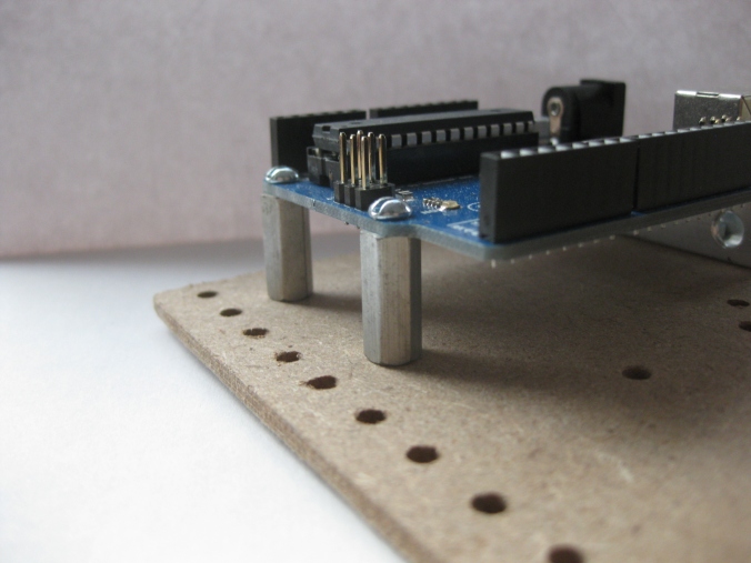
Arduino with Standoffs

Standoffs are a perfect example of column-separated plates

Another joinery technique is actually the subject of this project day: the half-lap rocket. The idea here is to cut opposing grooves in material so they fit together like a puzzle. When the two pieces are joined together, the structure will be very strong because a force that would bend an unsupported thin plate in half is being opposed by the other plate not wanting to bend along its edge.

One of my favorite projects lately has been some small MDF rockets made out of two cutouts in 1/8″ thick material. The outline of each one is identical and the only difference is that one piece has a slot from the top to the middle and the other has a matching slot from the bottom to the middle. When you put the two pieces together, the rocket is free-standing and 3-dimensional. The best part is, you can make the same figure with some MDF and a coping saw, just follow these simple steps!

1) Draw the object you are going to cut out. Feel free to make anything you like. The guiding principle for the rockets was to make them symmetric with the half-laps made on the dividing line. If you want to use my design to make a rocket ship, print this PDF.

2) Cut out the shapes. Make sure the cutouts are as clean as possible. They will become a stencil in the next step.

3) Trace the stencils onto your material. Remember, the slots won’t work unless the material and the slots are both about 1/8in thick. If your material is a different size, adjust the slot width to match. Make sure to leave some room around the tracings so your cuts in the next steps won’t start right next to the finished cutout.

4) Use a coping saw to cut between the two tracings and cut away most of the excess material. The idea is not to start cutting on the lines of the tracings, but rather to leave room so your cuts aren’t starting right next to the cutout in the next steps.

5) Using a drill, drill a 1/8″ hole at the end of each of the two slots, this will make it easier to finish them. If you don’t have a drill available, you can use a back and forth method to clear the material from the end of the slot in step 7.

6) Make your detailed cuts by cutting lines from the edges of your material to the sharp inside corners. Remember, coping saws can cut contours just fine, but it won’t cut hard angles easily and could even break your blade. Make multiple cuts to take the excess material away in wedges or strips.

7) Now that the exterior of the tracing is gone, cut the grooves. If you have a piece of thick scrap with a straight edge, you can clamp it to your cutout with the edge right on the line of the groove so as you cut, it will make sure the blade doesn’t go too far astray if you lose your line.

8) With the two halves of the rockets done, you can sand the edges smooth, put them together with a little glue in between, and you’re done!

If you’d like to add some finishing touches, you can paint them with a crazy design or add some LEDs for a more retro high-tech effect.

Bonus project!

 IMG_2420

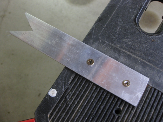
Coping Saw Guide made from 1/8″ aluminum bar

I find its best to use a cutting guide to improve the precision of my cuts and make life easier in general. You can make one with a long strip of scrap. Thick, rigid material is best. Mine is made from a scrap of aluminum plate. Cut a V in one end of the scrap at about a 60 degree angle and secure the other end to your work bench. As you cut, if you keep the saw blade close to the crook in the V, there will be more support on the material, so more of your energy will go into cutting and less into keeping the material flat on the edge of your bench, allowing you to control the direction of your cuts.

Using the techniques here, you can make a LOT of things from mini animals to project enclosures. The possibilities are as limitless as your imagination.

That was my project day, how was yours?

Did you like It’s Project Day? You can subscribe to email notifications by clicking ‘Follow’ in the side bar on the right, or leave a comment below.
Makers will have their Day

By Presidential proclamation, June 18, 2014 is the National Day of Making!


You can find details of todays first white house maker faire through the White House blog. (Thanks to Farzan for the nudge).

In honor of the day, go make something and share your project in the comments section below.

Did you like It’s Project Day? You can subscribe to email notifications by clicking ‘Follow’ in the side bar on the right, or leave a comment below.
Building memories with Dad

Happy Father’s Day (weekend)!

Some of my fondest project memories involve my dad. He gave me my first lessons in electricity, wood working, telecommunications, metallurgy, construction, and siege machinery. He showed me the right way to stain wood, cut plexiglass for model airplane propellers, and pick out the good lumber. I’m always thankful for the lessons I learned just by helping him work on his projects.

So take advantage of today and grab your sons and daughters and start a project with them. There are plenty of project ideas online that you could build with your kids. You would be surprised at how much that will develop them as people, teach them skills, and feel the joy of sharing the things you are interested in.

Here are a few suggestions to get you started:

Ripcord Rotor Chopper

Water Bottle Rocket

Wooden Tool Carrier

Did you like It’s Project Day? You can subscribe to email notifications by clicking ‘Follow’ in the side bar on the right, or leave a comment below.

Give aging technology a chance

 Think twice before throwing out your old tech. Perhaps that disused piece of junk can have a second chance in your next DIY project.

Let’s rewind the clock to 2001: NASA lands the first spacecraft on an asteroid, Gladiator wins the Academy Award for best picture, and Handspring releases the Handspring Visor Neo, the company’s affordable PDA competitor of the Palm Pilot. At the time, this baby was screaming (for hand-helds) with a 33MHz processor, 8MB of RAM and a high resolution 160×160 pixel gray-scale display. The following year, I was lucky enough to get this high-tech piece of portable technology as a barter deal for helping a neighbour understand how to use their own PDA.

I kept my Visor in working order over the years and it was still limping along when smartphones became affordable and I didn’t need it any more. After it was clear that my old friend was no longer useful as a practical tool, I looked into selling it on eBay, but found more equivalent devices that went unsold than sold so I had the choice of either throwing it out or trying to find something else to do with it. Since I’m not inclined to ‘e-waste’, I started digging around for potential ways I could repurpose it on the internet. Handspring made it’s niche in the PDA market with their springboard expansion slot, so I was really interested in figuring out how to hack it (the device has a docking interface and an IR transceiver, too). Given its age, I had a LOT of broken links to sort through, but I eventually found NS Basic Palm, Pocket C palm, Palmphi, and Palm OS Emulator. It took a while, but I was finally able to hijack the emulator from POSE and use a ROM that I found online to use for exploring the potential of the programming languages on the go. I found out that Handspring once had a development kit for the springboard expansion slot, but was disappointed to find that it was no longer available from Palm.

While I was excited at the prospect of writing apps for a new platform, I realized that there was no way I’d be carrying the Visor around with me on a daily basis, so aside from can-I-do-it curiosity, the Visor was doomed to be recycled. The turning point was when I discovered that the Handspring PDAs (and I suspect other Palm Pilots as well) used serial protocols to sync data with the PC. If you look at the circuit board inside the serial docking station, the connection is direct from PDA to PC. I suspect that the only addition the USB docking station brings is an FTDI. The most exciting discovery was that Pocket C had a couple functions allowing the Visor to establish the serial connection and push data independent of syncing. I suppose I should have figured that this was possible since the Targus Stowaway keyboard connected through the docking port. This was such a revelation: If serial comms was possible, then I could connect this little computer to anything with a serial port…  The possibilities were endless.

130608_CradleMod

A few wires and a Molex connector were all I needed to tap into the serial connections on the cradle


I decided that the best thing I could do was to relieve my computer of the burden of driving my Lynxmotion robot arm. Since the development software I had didn’t include objects like buttons and sliders, I created my own. Using basic drawing features like boxes, lines, and text, I was able to create a GUI with buttons, indicators, and a slider so I could engage the serial port and individually control each servo in the robot. In the process of developing my program, I realized that I needed a controller that could read data from sensors if I wanted the arm to do anything useful, so as it turns out the Visor wasn’t a good fit for the robot arm in the long-term, but the device had proven itself. Who knows what else I might be able to use it for in the future? Maybe it’s going to be my next universal remote control? I still haven’t figured out how to dig into the springboard expansion slot, but I suspect that it’s going to unlock an even bigger potential for my little friend. Perhaps the next step is to reverse engineer the GPS expansion I bought years ago, but could never get to work.

140608_Arm

My standalone robot arm with it’s new(ish) computer brain


The big lesson I learned here was your next project doesn’t have to start as $100+ in new electronics, maybe it starts with that old gadget you have laying around with lots of hidden potential.

That was my Project Day, how was yours?