As it turns out, you CAN make a CNC machine on a shoestring budget! It just takes a lot of time, reading, effort, and… time.
Taking the ThrAxis for a Jog
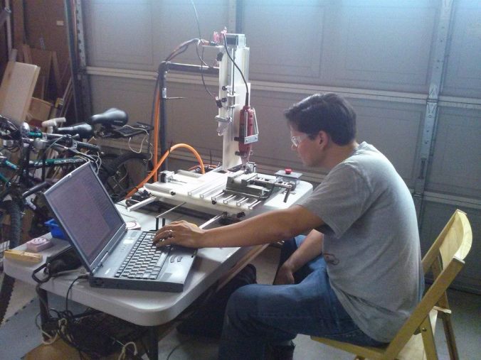
The ThrAxis (Three-Axis) is a vertical milling machine made mostly from materials from hardware stores. The spindle is a Harbor Freight rotary tool and the motors and controllers are surplus and eBay finds. We made it during lots of late evenings using mostly handheld power tools and “garage precision”. It was a fun project for me to work on with my wife and it’s become a handy tool. I’ve found that it has accelerated my ability to realize my project ideas and has made it much easier to make things with the personal touch. We’ve made toys, art, and mechanisms and we have plans for much much more.
 |
 |
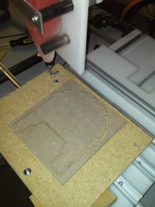
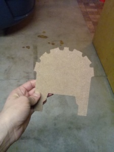
| Cutting out the Silhouette of a Lion Archway | Lion Archway Cutout |
Why would you make a CNC machine in your shop? It seems like such a daunting job and what the heck would you do with it when you got it? These are the questions I heard when I brought up the ThrAxis to most people. They were right to question because it’s not an easy job. Since working on projects is what I do for fun, the doing and the why were a given for me, but I found it hard to explain. CNC machining allows you to make amazing things; things more precise, rapidly, numerous, and intricate than a person could make by hand. Of course you’re limited by a spinning tool and how far your machine can move, but it’s way more capable than a handsaw and a Dremel tool. My first inspiration was bloodying my fingers forever bending little 1/2″ long wires for RadioShack prototype circuit boards, then chemical etching circuit boards by hand (having only about a 10% success rate), and then spending $100+ on professionally-made circuit boards made me realize that there has to be a better way to get my ideas from breadboard to circuit.
First, there was the ‘buy a CNC machine online’ fiasco. Basically, I saved up a lot and found a few companies online who were selling CNC milling machines. I found one that was in my price range, but the lead time was months. BIG MISTAKE. And I had to pay the full amount up front. RED FLAG. I didn’t hear a peep for a while (eek!) and when I finally reached out, I got no response. I thought my money was safe because I used PayPal to send it. Wrong again! PayPal only guarantees purchases made on eBay. Eventually, I used the refund processes in PayPal to get my money back and got very very lucky, but my experience definitely left a bad taste in my mouth.
Then I started to think seriously about making one on my own. Mostly, though, I blame Make Magazine for my inspiration to do it myself. Since the first issue of my subscription, I’ve seen featured projects for dozens of gantry-style CNC router tables. Throw in the discovery of surplus electronics websites like all electronics and goldmine electronics and I was on a collision course. The final straw was finding the instructable article by Tom McGuire. We liked his design because the boom-style tool holder seemed more stable than the gantry-style CNC router projects we had seen (necessary for making circuit boards). It also has fewer moving parts than the gantry-style CNC routers which means fewer bearings and fewer opportunities for misalignment. The use of the inexpensive rotary tool instead of a router was also a big deal because it meant we could build something that would fit in our tiny workshop. After a couple of coffeehouse design sessions with my wife, we had some plans and bought the parts to get it done.
I’d been toying with the idea of making a CNC mill for years, but to get this project up and running took about 4 months from drawing up plans to cutting out a part, $250, and a dozen stops at the hardware on the way home from work. Just like the reference instructable, the frame is made from black steel pipe, the stages are made from HDPE, and the screws are 1/4″-20 threaded rods. We added our own features and changed the size of the shapes around to suit our needs, though. We opted for some thinner, leaner materials in the interests of cutting costs. We also took some other liberties with the design, for example the use of 1/4″ fuel line as a motor coupler didn’t seem like a winner, so we used some 1/4″-20 threaded couplers half drilled out with set screws in the shaft section instead. My favorite feature is the bearings: they are actually skateboard wheel bearings. We got a box of 8 of them for $12!
Here’s a brief bill of materials of what we used:
- 3/8″ HDPE sheet for all of the stages
- 3/8″ architectural C-channel for the linear guides
- 1/4″-20 threaded rod for the linear drive screws
- 3x 1/4″-20 couplers for linear drive nuts
- 3x 1/4″-20 couplers half-drilled out to 1/4″ with #6-32 set screw hole for motor coupler
- 8x skateboard wheel bearings
- lots of washers to level the stages
- 2′ x 2′ sheet of 1″ MDF for a foundation
- 3x 3.5A stepper drivers from AutomationDirect
- Power supply for stepper drivers also from AutomationDirect
- circuit breaker
- logic level converter built around a 74LV125AN buffer
- E-stop button
- 6 limit switches
- Shielded cable for stepper motors
- 6′ of T-slotted track
Fortunately, there is so much material online regarding CNC milling and making CNC machines that we were able to get over almost all of the little roadblocks. We were able to assemble it using hand tools, a cordless drill, drill press, a level, and a roofer’s speed square. We had a few occasions to use some taps, too. We are using the TurboCNC software graciously provided to the community for free by DAK Engineering to interpret the g-code on a Windows 95 laptop (a dinosaur, to be sure) which sends the commands through the parallel port to a scratch-built voltage logic level converter to step it up from 3V output to 5V, then into the stepper driver cards. The reason we are using the Windows 95 computer is because we have it and the free TurboCNC software runs in DOS mode, which isn’t available on modern computers.
After we got it running, the first part I made was a raised ‘E’ logo that I use to mark my prototypes. That was my wife’s idea. It was a good test of the ThrAxis’s capabilities because it used rapid moves, drilling, full tool width cutting engagement, circular cutting operations, and excess material removal. The finished part wasn’t too complicated, but it had three different elevations, so that was an achievement. After that I was hooked and just wanted to crank out parts, so I started out doing cutouts of flat materials. I made a few fixture plates for a mobile robot I’m working on and made a few other parts for around the shop. My favorite is a fixture for a cellphone holder so I can rock out and charge my phone while I’m hard at work on the weekends. My wife and I have also done some cutouts of the half-lap rockets from last week’s post. Those are fun because you can make little changes to make the rockets unique and for the most part, the GD&T isn’t important with artistic cutouts. Right now, I’m working on cutting out circuit boards (my first goal of having a CNC machine) and the attempts are teaching me a lot about runout, backlash, tool condition, stage flatness, and feeds and speeds. So far, I’ve broken two tools, but I know why they broke and that makes the experience worth it. I’m also learning about the details about machine code: how the command structure changes with the software that generated it and how the interpreter software sends those commands to the machine. Just a bit of advice: complication goes up exponentially as the part size goes down, so be prepared. It cuts soft materials like wood, MDF, and expanded plastics really well, but I’ve been having problems with cutting solid plastics. I think we have a torque deficiency in the rotary tool, so I haven’t tried to cut solid aluminum or copper yet, but maybe some day.
ThrAxis Machining a demo part
Given that my wife and I didn’t have machine tools to manufacture precision parts before we built this, there’s nothing I would go back and do differently. Moving forward, however is a different story entirely. We’ve been making small modifications to the machine since we built it. So far, we’ve added screw cover bellows and a vacuum system to keep the dust down. I’d like to replace the rotary tool with a better spindle. The rotary tool doesn’t have a lot of torque and very little speed control, so some more power and the ability to regulate speed are key improvements to improving it’s cutting ability. I’d also like to improve the guides to improve position accuracy. I’m not sure yet if that means adding more bearings for the guides to ride on, changing the motor couplers, or replacing the nuts we use for moving the stage with a more rigid assembly, but there is room for improvement. I’d also like to figure out a better way to transfer programs to the Windows 95 laptop. Bear in mind, this is pre-USB and wi-fi, so there’s no simple way to do the file transfer.
That was my project day, how was yours?
Did you like It’s Project Day? You can subscribe to email notifications by clicking ‘Follow’ in the side bar on the right, or leave a comment below.

About transfering files to the laptop, why don’t you try a card reader? I found one the seller states it works on 95 & DOS: http://www.ebay.com/itm/NEW-SCM-Smart-Card-Reader-Writer-PCMCIA-PC-Card-SCR-201-SCR201-/281022831274?pt=LH_DefaultDomain_0&hash=item416e441aaa
This design with fixed Z axis is quite interesting for one particular reason: vertical clearance. How stable you found it to be? I could even have it done with three bars if it made that removable without losing performance.
Thanks for the tip, Fernando. I hadn’t considered using an SD card.
Actually, the cantilever arm is quite strong. Since the picture was taken, we’ve shored it up, but only because we mistook spindle overload for machine flex. You are absolutely right, though, the more clearance you build into the machine, the more risk there I’d of machine flex.
I’m sorry I wasn’t clear in the post, but the stability concern I had was in regards to the typical gantry design which has two shuttles (one on each leg of the gantry, where it meets the guides) that have to translate in unison. It seems like if they are out of alignment you could get premature wear, stepper motors skipping due to overload, and some bad parts made. At the end of the day, though, it’s all about preference.
Pingback: $250; Pushing The Limit On Cheap (And Functional) CNC Machine Builds
Pingback: $250; Pushing The Limit On Cheap (And Functional) CNC Machine Builds - Tech key | Techzone | Tech data
Pingback: $250; Pushing The Limit On Cheap (And Functional) CNC Machine Builds | Hack The Planet
Pingback: ThrAxis DIY CNC mill | RLabs
Pingback: Entry into Machine Vision | It's Project Day!
Pingback: Fume Extractor | It's Project Day!
Pingback: Machine Learning Color Classifier | It's Project Day!